Cornerstones Unified Database Design ProjectSYST 699: Fall 2014 | ||||||||
 |
| |||||||
DesignOnce the use cases and requirements were developed, our team had a full understanding of the data that Cornerstones needs to capture and the reports they needed to generate. The next step in the systems engineering life cycle was to take the results of this analysis and begin to design the system. In this case, the system we would be delivering was a unified database. The database design was conducted using a three stage database design process. These stages are conceptual model design, logical model design, and physical database model. The following sub-sections will describe each design stage.Conceptual ModelDevelopment of the conceptual model was the first step in our design process. The purpose of the conceptual design was to capture a high-level understanding of the information used in Cornerstones’ operations of the Neighborhood Resources program. A model of this information was drafted by identifying the entities involved in these operations, and the relationships they have with each other. The conceptual design is independent of all physical consideration, and is only concerned with the entities and their relationships.The conceptual design was created using entity-relationship models, and diagrams for these models were developed using the Visual Paradigm software. It is presented below: 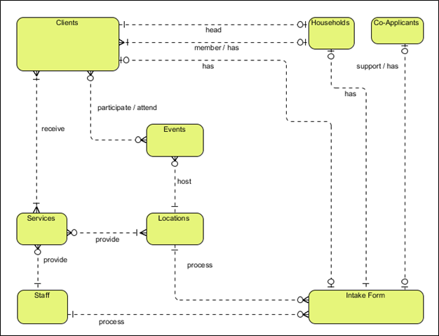 The lines connecting the entities in the diagram above represent the relationship between the entities. The types of relationships can be one-to-one, one-to-many, many-to-many, and so on. A full description of each relationship presented in the conceptual design can be found in the Final Report. Once the design was drafted, the GMU Team reviewed this design with Cornerstones. We received all feedback, addressed deficiencies or inconsistencies between our design and the way Cornerstones staff understood their processes, and then redelivered a final conceptual design. Logical DesignThe logical model takes the conceptual model and begins to define the elements that are a part of each entity. For example, the “client” entity may contain elements such as name, address, date of birth, race, member of household, etc. The logical models were created using entity-relationship models and diagrams were developed. The elements in each entity were identified through our analysis process (Section 3), as well as data captured from the working group meetings with Cornerstones.The logical design was created using entity-relationship models, and diagrams for these models were developed using the Visual Paradigm software. It is presented below: 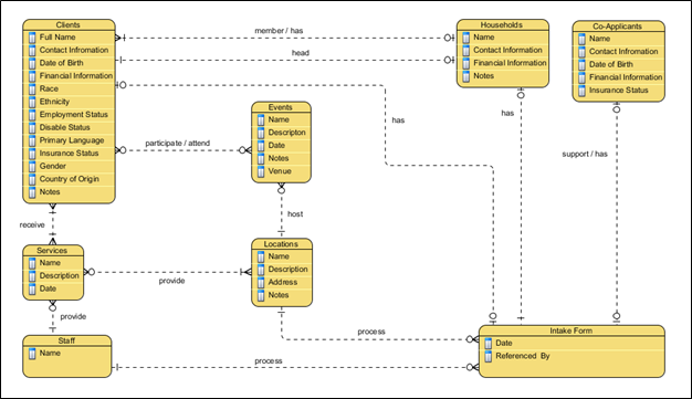 Physical DesignThe purpose of the physical design is to provide an architecture framework that can be understood by a database management system. For the Cornerstones Unified Database, our team decided to use MySQL as the relational database management system. MySQL had many advantages over other systems. Some of these advantages are: (1) open source, so cost is free and it is available under the terms of the GNU General Public License; (2) widely used, so there is familiarity with the system by all potential users and maintainers of the database; (3) fully supported, being an open source product allows access to useful updates and support of the system throughout its lifetime, as well as being fully operable on many types of operating systems; (4) well documented, and (5) proven to be a robust platform for database management.In order for the MySQL relational database management system to understand how to handle the data in the database, it relies on a physical design. The MySQL Workbench tool was used to develop our physical database model of the Cornerstones Unified Database. It is presented below: 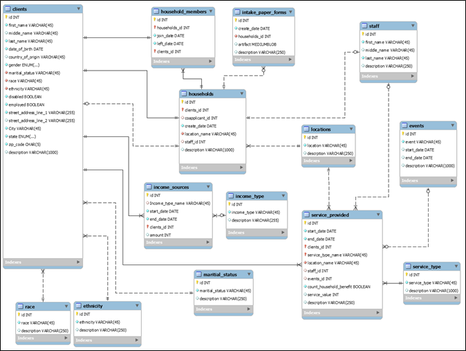 The physical design takes the logical design and provides rules around the behavior and content of the elements. In addition, it enforces the relationships amongst entities as defined in our conceptual model. The physical design also allows us to assign primary keys for each entity, giving us the structure for creating unique client IDs, households, Cornerstones locations, services provided, etc. Additional details about the physical design are presented in the Final Report. Tools EmployedSeveral tools were used by the team during the design process. Tools were also used during the testing and deployment of the unified database. A description of these tools is listed in the table below. The “Function” column listed in the table shows what phase of this project each tool was used in. To aid Cornerstones during the operation of the unified database, we also developed a set of installation instructions for the tools, which are found in the Final Report.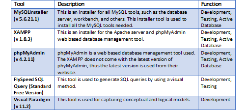 |


| Thank you for visiting our page! |